West Fargo, ND – Storm Lift Stations
Challenge
The City of West Fargo was experiencing rapid growth and development in sections 19, 20 and 29. These three sections are flat, as is typical in the Red River Valley. The Sheyenne River at 32nd Ave. E. varies in elevation, with a channel elevation of 885 and a high water elevation in 2010 reaching 904. The Sheyenne River had sustained elevations of 892 and higher for over a year, partially due to the discharge of water from Devils Lake. Storm lift stations were needed to ensure that water drained properly from the three sections.
Sections 19, 20 and 29 soils consist mainly of clay formations which extend to depths of approximately 100 feet. The deeper layer is the Brenna formation, which is a gray, fat clay with low blow counts. The shallower layer is the Sherack formation, which is a firmer, tan clay. Both clay types are prone to shear failure and sloughing. Constructing lift stations or installing utilities near the river present engineering challenges due to the weak soils. Due to the weak soils, keeping the lift stations as shallow as possible was preferred, as well as not adjacent to the river due to sloughing issues.
Solution
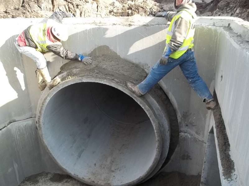
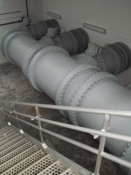
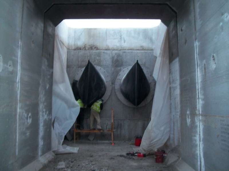
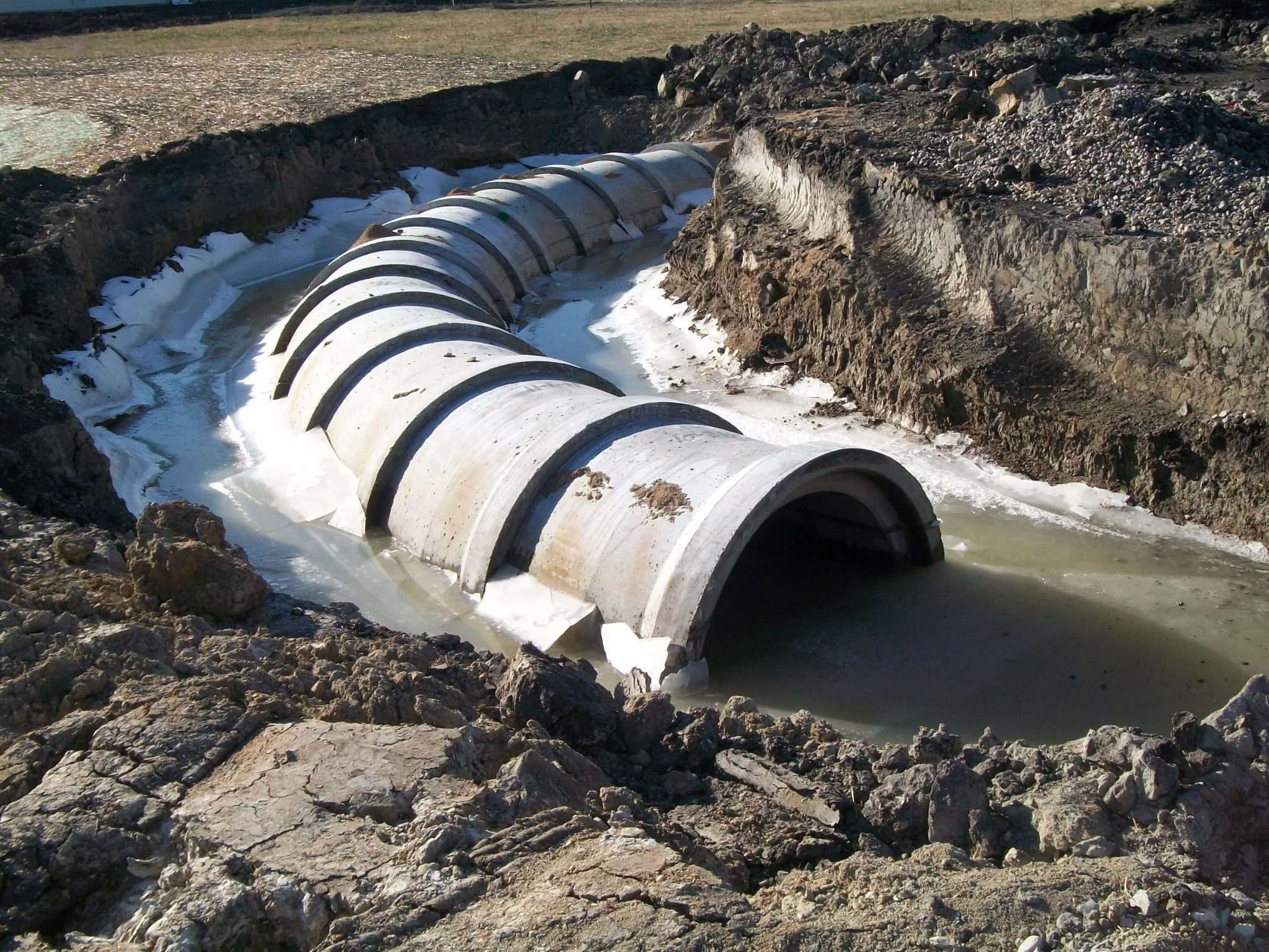
Section 19 Lift Station: Moore Engineering designed a lift station for Section 19 with a peak capacity of 107 cubic feet per second (cfs). It features 550 feet of 8-foot by 6-foot reinforced concrete box (RCB) from an existing pond and allows future ponds to connect. At a manhole, the pipe transitioned to an 84-inch diameter reinforced concrete pipe (RCP), of which 654 feet was installed. The last 90 feet of pipe to the lift station was a 7-foot by 7-foot RCB that used long radius bends to make a 90 degree turn into the building. The downstream side of the lift station has a 48-inch RCP force main. The outfall structure to the Sheyenne River consists of a precast concrete vault with a duckbilled check valve, followed by a 7-foot by14-foot RCB with a sloped end section. The vault was located at a natural bend in the river to minimize the possibility of scouring the opposite river bank if the lift station was operating at peak capacity.
The 48-inch force main had to be installed under Sheyenne St. to get to the river. A detour plan was created to redirect vehicle traffic in order to allow for the construction activity of the force main under the road.
Section 20 Lift Station: A lift station was designed for Section 20 with a peak capacity of 160 cfs. An 84-inch RCP was connected to an adjacent storm water pond. The downstream side of the lift station has 3,800 feet of 60-inch RCP force main.
Section 29 Lift Station: A lift station was designed for Section 29 with a peak capacity of 160 cfs. An 84-inch RCP was connected to an adjacent storm water pond. The downstream side of the lift station has 3,800 feet of 60-inch RCP force main.
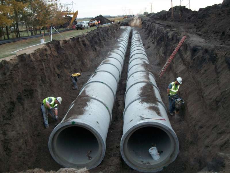
The force mains for sections 20 and 29 run parallel, two feet apart under 32nd Ave. E. Controlled density fill was placed between the two pipes as proper compaction would not be possible below the spring line of the pipes. The 60-inch force mains had concrete thrust blocks poured at locations where large radius bends were used.
A single 16-foot by 16-foot precast concrete vault was used at the Sheyenne River for the two 60-inch force main outfalls. Each force main had a duckbilled check valve. The downstream side of the vault had a single 14-foot by 17-foot RCB with a sloped end section. This RCB day lighted at a 45 degree to the river channel to minimize the possibility of scouring the opposite river banks if both lift stations were operating at peak capacity.
The city requested that the three lift stations be as similar as possible, including layout, controls and exterior building construction. Moore Engineering designed the lift stations to pump the allowable peak discharge rate for the 24-hour, 100-year storm. The sections had existing storm water ponds to allow for live storage volume to accommodate the 100-year storm, with additional pond storage planned for additional development in the future. The section 19 lift station has three 100 horsepower (hp) pumps. Sections 20 and 29 have three 200 hp pumps. Sections 20 and 29 also had a fourth, 15 hp submersible pump for smaller storm events, which would prevent excessive pump cycling of the larger pumps. Section 19 did not need the fourth pump as the storm water ponds in section 19 could allow a higher bounce before the pumps turned on. This would allow higher flows to the lift station, reducing pump cycling.
Project Outcome
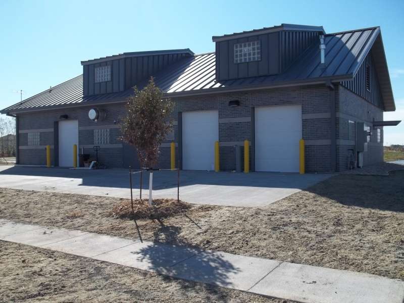
Three 65-foot by 40-foot lift station buildings were constructed and the project came to completion nearly three months early.